Resurrecting a Heathkit HP-13
As seen in my previous post I've taken the dark plunge into the world of tube radios. I want to start restoring my Heathkit HW-101, but before I can do that I must be able to power it. As I previously wrote, I taken the road less travelled and got an old (circa 1965) HP-13 mobile power supply because I thought it would be nice to power the radio from a 12v source rather than mains.
 |
| Unrestored HP-13 with broken solder joints and trashed capacitors |
Well there seems to be a reason these don't seem very popular... I'll get to that.
I found a very nice article from RDF-Electronics regarding modernizing the HP-13 power supply. That document includes the components and part numbers for everything you will need to restore your HP-13. My parts arrived from Digi-key and I began snipping and desoldering the old component off the PC board. The replacement electrolytic capacitors are all much smaller and have radial rather than axial leads. That makes placing things on the board require a bit more creativity.
 |
| HP-13 Schematic |
The only truly problematic components to replace was replacing the twin positive axial lead electrolytic (C11) with two electrolytic capacitors (space issue) and replacing the C1 and C12 due to the tricky wiring around the transistors.
 |
| The orange cap on the left under the Q1 (C1) was tough to replace with a much smaller radial lead capacitor |
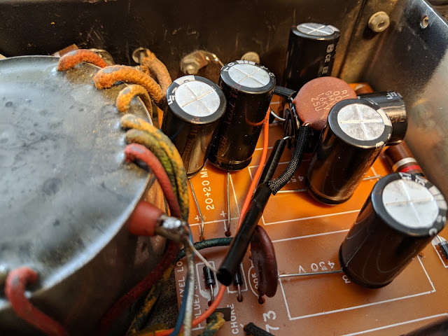
The article suggested replacing the original 100 uF/50 V capacitor with a 4,700 uF/35V to better control ripple. The article goes into quite a bit of detail concerning his testing of ripple using an oscilloscope. Finding room for that big cap and it's accompanying filter disc required a bit of creativity as seen below, where it's laying on its side between two of the rectifier caps.
I will glue all the caps to the board before I put the power supply into service.
New capacitors and diodes
I replaced all the electrolytic caps and diodes. The diodes might have been ok but they are blocking over 300 volts each and a single failure would let the smoke out for sure.
 |
| Out with the old |
 |
| In with the new |
All the resistors except one 100k 2 watt were ok. So I only replaced that resistor. The 1.6kv disc caps even measured ok.
The internals look a bit different now with the new caps standing up where the old, larger axial lead components laid flat.
 |
| Ready for testing |
Testing
After performing resistance and continuity checks I buttoned it up for the test.
The Noise
I had no idea how audibly noisy this power supply would be. The switching that occurs in the transformer creates a very loud whine. I understand why hams would install these in the trunk. There's no way you'd be able to stand this for long if it was sitting next to your station.
I have a longish intro in the video. Skip towards the end to hear it powered up... turn your volume down when you see the "hearing protection" sign come up in the video.
Conclusions
This was a good learning experience. I learned about high voltage transformers and got some practice restoring older equipment. I practiced electrical safety and didn't kill myself, so I'm pleased about that.
I now have a power supply I could use from a sturdy 12v source if I needed it, BUT due to the noise in operation I'm going to look into restoring a HP-23 which runs off house mains (AC) and is mostly silent.
I'll keep this on the shelf waiting for a day that I need to run the HW-101 mobile.
That's all for now
73
Richard AA4OO
